| |
|
|
| |
|
|
(9) LinearStrip Panoramic Turntable Version 2 (BX-24)
This entry describes how to build a linear-strip panoramic turntable using a Vex Robotics gear kit, a Howard Industries (P/N 1-19-3801) 12 volt stepper motor, a BX-24 microcontroller, and a ULN2004A integrated circuit. This section also discusses the Mac OS X software used convert the video panorama into a single image panorama. The pan speed is slowed down to strip out one column of pixels every 30th of a second for each video frame. The column of pixels are written out to a raw binary file and eventually converted into a TIFF image.
|
|
| |

|
|
| |
|
|
(8) LinearStrip Panoramic Turntable Version 1 (BX-24)
This entry shows how to use an old Xerox WorkCentre 450c fax machine to make a turntable for linearstrip and panoramic imaging. For this project I hacked the stepper motor (and gear assembly) that moves the Xerox paper through the scanning array. Because the motor had 5 wires I identified it as a unipolar stepper motor. These motors can be driven with a ULN2003A integrated circuit and a low cost BX-24 microcontroller.
|
|
| |
|
|
| |
|
|
(7) Networked Lamp (PIC)
This entry describes how to connect a Lantronix Cobox-Micro to a Java server over a local area network. In this example we use a PIC 18F452 microcontroller, some blue superbright LEDs (http://www.superbrightleds.com Part# RL5-B2430) frosted plexiglass, three RadioShack project boards, and a Sharp GP2D120 proximity sensor to build a lamp that responds when viewers walk up to it.
|
|
| |
|
|
| |
|
|
(6) Connecting a PIC 16F819 to a Cobox-Micro (PIC)
This project describes the setup used to connect two Lantronix Cobox-Micro servers over the internet. The user pushes a button connected to a PIC 16F819 microcontroller and an LED lights up on the other, remote, Cobox and vise versa. The figures below show the breadboard layout. A hex inverter was used to amplify the signal coming from the PIC microcontroller.
|
|
| |
|
|
| |
|
|
(5) Serial Input to a Terminal (BX-24)
This circuit uses the BX to send bytes to the terminal. In this case I used a momentary pushbutton to put an ASCII character "1" on the screen. When the button is not pressed the ASCII character "0" is shown. To get these characters to display on screen, the BX actually sends out the ASCII numerical value. For example, when the button is not pressed we send the number 48 which corresponds to char "0". When the button is pressed we add 1 and get 49, which corresponds to the char "1".
|
|
| |
|
|
| |
|
|
(4) Driving a Bipolar Stepper Motor (BX-24)
This entry shows the configuration I used to make a NMB (Minebea Electronics Co.) PM35L-048, 24VDC, 9.4 Ohm bipolar stepper motor work. I salvaged several of these motors from some Xerox inkjet printers. The motor was well labeled and I found manufacture specifications on-line. I was not able to find a wire diagram so I defaulted to making a truth table as I had done for unipolar steppermotors. Most steppers with 4 wires can usually be identified as bipolar stepper motors, which can be driven with a dual H-bridge IC such as the SN754410 by Texas Instruments.
|
|
| |
|
|
| |
|
|
(3) Driving a Unipolar Stepper Motor (BX-24)
This entry shows the configuration I used to drive a unipolar AstroSync 12VDC, 130 Ohm stepper motor. I bought two of these motors somewhere off of Canal St. and had no idea about their specifications or even if they worked. I did know a few things based on some earlier reading. First, most steppers with more than 5 wires can usually be identified as a unipolar stepper motor, which can be driven with a ULN2003A.
|
|
| |
|
|
| |
|
|
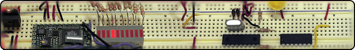
(2) Memory, Variables and Edge Detection (BX-24)
The purpose of this circuit is to read input from a switch and illuminate five LEDs in a particular sequence based on the number of times the switch is pressed. Thus, the first time the switch is pressed the LED to the far right is illuminated. This sequence is repeated each time the switch is pressed until the 5th LED is illuminated. The fifth time the switch is pressed a buzzer sounds and all five LEDs are turned off. The user can then repeat this process.
|
|
| |
|
|
| |
|
|
(1) Analog Input (BX-24)
Inputs to microcontrollers can be in two forms. Analog or digital. Analog is most intuitive because this is the kind of input we get from our senses such as sound, light, touch etc. Analog is typically described as a continuous set of values instead of a single on/off response (digital). In this example I have wired up a 5kOhm potentiometer (pot) to pin 13 of a BX-24. Note that the black wire from the pot goes to ground, the yellow wire goes to 5VDC, and the red wire goes to pin 13 of the BX-24.
|
|
| |
|
|