 |
| home | eyetracking | computing | aesthetics | research |
| software -- microcontrollers/breadboards -- generative algorithms |
|
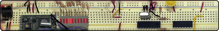
Connecting a PIC 16F819 to a Cobox-Micro (PIC): This project describes the setup used to connect two Lantronix Cobox-Micro servers over the internet. The user pushes a button connected to a PIC 16F819 microcontroller and an LED lights up on the other, remote, Cobox and vise versa. The figures below show the breadboard layout. A hex inverter (the center 16pin chip) was used to amplify the signal coming from the PIC microcontroller. In this example we use COM3 on the BX to put values out on a terminal program, in this case Zterm, which used to be free, but now you can download it here for $20. Connect Serially to the Cobox to configure To configure the Cobox for the first time you must connect to it serially via RS232. Programs such as Hyperterminal or Zterm (Mac) can be used to activate the configuration menu. Once the cobox is connected serially (see below) then hold down the "x" key while pressing the reset button on the Cobox. A text-based menu should showup in the terminal application's window. A summary of the configuration we used for both coboxes is as follows IP address: as given to us by the network administrator Gateway address: as given to us by the network administrator Netmask (number of bits for host port): 8 (equates to 255.255.255.0) Channel 1 settings (main menu item1) This configures how serial port 1 will work, and how you'll connect to it from the net: Baudrate: 9600 I/F Mode: 4C (sets the various baud mode bits; see manual for details) Flow: 00 Port No: 10001 (or whatever other port number you choose) Connect Mode: C4 or D4 (or C5 or D5 for auto-connect) Remote Address: address of whatever machine you want it to connect to automatically on startup (works only if connect mode is C5 or D5) Remote Port no.: 10001 i.e. the port number to connect to on that remote machine Disconnect mode: 00 Flush Mode: 77 Disconnect Time: 00:00 SendChar1: 00 SendChar2: 00 Connecting the PIC to the Cobox The figure below shows how the PIC is connected to the Cobox. In this example a hex inverter is used to amplify the signals coming from the PIC. A pushbutton switch is connected to port B4 of the PIC for input (note the 10k pull down resistor on the switch). A jumbo yellow LED is placed on port B5 and a red led is placed on port ?? (note the 220k resistors for the LEDs). When the user pushes the button on one of the Cobox servers, the LED on the other Cobox illuminates. Transmission (TX) from port A2 on the PIC goes to the output pin4 on the hex inverter. Receive (RX) from port A3 on the PIC goes to input pin1 on the hex inverter. The output pin2 from the hex goes to the RX input pin3 on the Cobox, and the input pin3 from the hex inverter goes to the TX pin4 of the Cobox. Port A4 from the PIC is connected to RTSA pin5 on the Cobox. 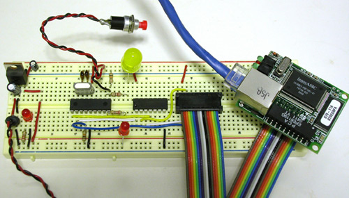 Figure 1 - full breadboard with all the components
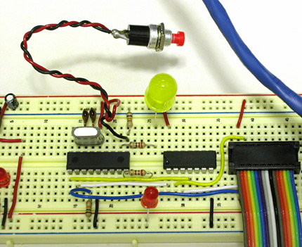 Figure 2 - closeup of the cobox setup
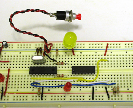 Figure 3 - closeup of the cobox setup with cobox cable (rainbow ribbon) removed.
'***************************************************************
'* Name : touch_go.BAS
'* Author : Jason Babcock
'* Date : 9/27/2004
'* Version : 1.0
'* Notes : PIC model 16F819
'* : USE THE SMALL ZIF socket for this chip (why I'm not sure, but the
'* : larger ZIF socket does not work)
'* : MAKE SURE TO SELECT "HS" when because oscillator is 20 MHZ
'****************************************************************

define OSC 20
'baudmode for serin2 and serout2: 9600 8-N-1 inverted
inv9600 con 16468

'define LED on/off values
led_on con  1
led_off con 0
ADCON1 = %10001110      'set ADC ports

'define the LED on/off variables
dataByte VAR BYTE
myStatus var byte

'define the tx and rx ports from the PIC (which go to the cobox)
tx      var     porta.3
rx      var     porta.2
switch1  var portb.4

led_yellow VAR portb.3  'put a YELLOW led on this port with a 220 ohm res
led_red  var portb.5   'put a RED led on this port with a 220 ohm resistor

':::::::NOTE:::::: the other coboxe must start with a myStatus of 1
myStatus = 0
'myStatus = 1


INPUT switch1       'define a switch on this port (getting input)
                    'Note: switch goest to +5V with a 10k resistor to ground
                    'the resistor comes after the switch

OUTPUT led_red
OUTPUT led_yellow

'initialize the output ports to low
high led_red
pause 2000
LOW led_red
LOW  led_yellow

main:

	 if myStatus = 1 then
        if switch1 = 1 then
            serout2 tx, inv9600, [led_on]
			myStatus = 0
            GOSUB blinkyellow
        endif

     else
       'if switch is zero
        serin2 rx, inv9600, [dataByte]

        if databyte = 1 then
            myStatus = 1
            GOSUB blinkred
        endif

	  endif

goto main

blinkyellow:
     HIGH led_yellow
     pause 500
     low led_yellow
     pause 500
RETURN

blinkred:
     HIGH led_RED
     pause 500
     low LED_red
     pause 500
RETURN
|
| Copyright © 2006 Jason Babcock. All rights reserved. | Valid CSS Valid XHTML 1.0 |