 |
| home | eyetracking | computing | aesthetics | research |
| software -- microcontrollers/breadboards -- generative algorithms |
|
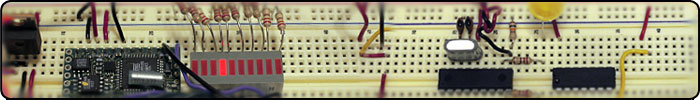
Linear-Strip Panoramic Turntable (BX-24): Introduction: Linear-strip imaging is a technique that records the scene (or moving sequence) a single line at a time and then stitches these lines together to form an image. The tabletop flatbed scanner is a common digital linear-strip imager. Linear-strip imaging systems are also used in aerial photography and satellite imagery. The technique described here was inspired from the work of Professor Andrew Davidhazy, who was my undergraduate professor at Rochester Institute of technology. Please visit his website for a comprehensive description on several linear-strip and panoramic imagers (http://www.rit.edu/~andpph). Stepper Motor This section shows the configuration I used to make a PM55L-048-KSC7 NMB, 74 Ohm, unipolar stepper motor work as a turntable for linear-strip/panoramic images. This motor was taken from an old Xerox WorkCentre 450c fax machine. For this project I used the stepper motor with the gear assembly that moves the paper through the scanning array. Because the motor had 5 wires I identified it as a unipolar stepper motor. These motors can be driven with a ULN2004A integrated circuit and a low cost microcontroller. The ULN2004 is an array of Darlington transistors which can take small input current from a microcontroller (in our case a BX-24) and use this to step the motor in a particular sequence. One of the first things I did was figure out how the stepper's wires were configured by measuring the resistance of each wire (as compared to all other wires) using a multimeter. I made a truth table as shown below (note that all values are in Ohms and inf stands for infinite resistance):
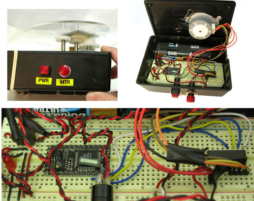 Figure 1 - Breadboard circuit and panoramic motor assembly
Wiring the Stepper Motor: Based on the truth table I found the coil pattern to be 36 Ohms between the orange to red2, yellow to red2, brown to red1, and black to red1. A total of 73 Ohms resulted between black to brown, and orange to yellow. This is illustrated in the figure below. 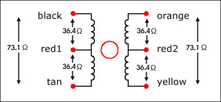 Figure 2 - Stepper motor wire configuration.
ULN2004A: The next step was to connect the proper wires from the stepper motor to the ULN2004A Darlington transistor. The next figure shows how this was done.The outer coils, orange, yellow, tan, and black are connected to the output pins (16-13) of the ULN2004A. Pin 9 of the ULN2004A is connected to the +12VDC supply. Note that wires red1 and red2 are also connected to the +12VDC.  Figure 2 - ULN2004A, BX-24, and unipolar stepper motor pin configuration.
BX-24 Microcontroller: Note the stepper motor requires 12 volts so I used 8 AA batteries and wired the power supply in parallel so that the stepper motor and ULN2004 get 12 volts, and the BX-24 gets 12 volts regulated down to 5 volts. The I/O pins from the BX-24 are connected to the ULN2004A as shown in the last figure. I used the code below to step the motor in the proper sequence. The BX-24 code is presented below:
dim motorStep(1 to 4) as byte
dim thisStep as integer

sub main()
  call delay(0.5) ' start program with a half-second delay
  dim i as integer

  ' save values for the 4 possible states of the stepper motor leads
  ' in a 4-byte array. the stepMotor routine will step through
  ' these four states to move the motor. This is a way to set the
  ' value on four pins at once. The eight pins 5 through 12 are
  ' represented in memory as a byte called register.portc. We will set
  ' register.portc to each of the values of the array in order to set
  ' pins 9,10,11, and 12 at once with each step.

  motorStep(0) = bx0000_1010
  motorStep(1) = bx0000_0110
  motorStep(2) = bx0000_0101
  motorStep(3) = bx0000_1001

  ' set the last 4 pins of port C to output:
  register.ddrc = bx0000_1111
  ' set all the pins of port C low:
  register.portc = bx0000_0000

  do
   ' move motor forward 100 steps.
   ' note: by doing a modulo operation on i (i mod 4),
   ' we can let i go as high as we want, and thisStep
   ' will equal 0,1,2,3,0,1,2,3, etc. until the end
   ' of the for-next loop.

   for i = 1 to 100
     thisStep = i mod 4
     call stepMotor(thisStep)
   next

  ' move motor backward
   for i = 100 to 1 step -1
     thisStep = i mod 4
     call stepMotor(thisStep)
   next

  loop

end sub

sub stepMotor(byref whatStep as integer)
  ' sets the value of the eight pins of port c to whatStep
  register.portc = motorStep(whatStep)
  call delay (0.1) ' vary this delay as neede to make your stepper step.
end sub
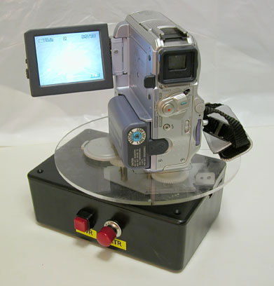 Figure 3 - Using the panoramic turntable with a miniDV digital camcorder.
Image Capture and Processing: To make the system mobile I use a Sony Mini-DV camcorder (DCR-PC105). I mount the camera on the spinning table and record the video stream onto the DV tape. The pan speed is very slow (usually about 3 minutes to do a full 360 pan). The pan speed is limited because of the software that I use to "strip"out the columns in the image to make the still panorama. This code will be available soon as I am still trying to fix some bugs and add a nice user interface to the software. <-- back to microcontrollers/breadboards |
| Copyright © 2006 Jason Babcock. All rights reserved. | Valid CSS Valid XHTML 1.0 |